Sound engine
Orbiter
Orbiter is at the heart of Vector. Each Corner (6) of the universe,
or rather, the two-dimensional space (1), is formed by two
Overtone Generators, Overtone Blend, and a filter.
The space also contains two orbs, blue (4) and green (5).
The blue orb follows a given trajectory within the two-dimensional space, which
is determined by Warp.
The green orb orbits around the blue orb in a circular motion. This motion is
referred to as Suborbit and its speed can be synchronized to the main
Tempo.
Suborbit Size and Suborbit Speed can be controlled by dedicated knobs.
The whole mechanism is called the Orbiter.

When a note is triggered, all four Corners play simultaneously and the final mix point of their outputs is determined by the green orb’s position.
The centre point (2) as well as the rotation and size of the Orbiter trajectory
can be set from the touchscreen interface.
When Retrigger  is enabled, the Orbiter motion always starts from
the beginning of the shape – its zero phase
is enabled, the Orbiter motion always starts from
the beginning of the shape – its zero phase (3) – on note input or after each
cycle of the Arpeggiator sequence. Note that the zero phase can be changed by
Warp.
Hints
To control the movement of the Orbiter manually, press the Focus button once to stop the Orbiter movement along the warped trajectory.
The centre point of the Orbiter can be also controlled by MIDI Control Change (CC) messages.
If your MIDI controller supports aftertouch or MPE, try Routing it to Suborbit Speed.
Corners
Corners are the origin of sound synthesis in Vector.
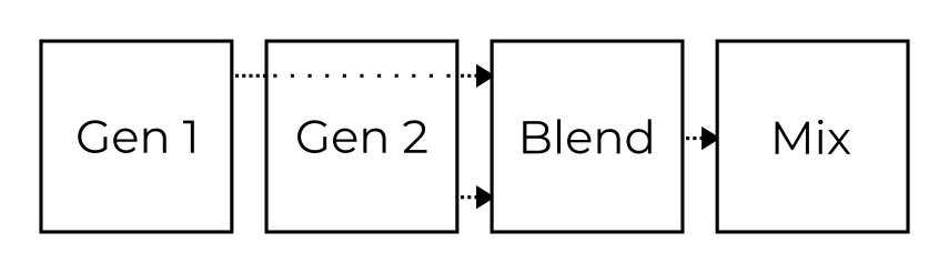
Each of the four Corners consists of two Overtone Generators with six specific overtone patterns. The two generators are combined by the Blend element – additive in the first half (G1+G2), modulated in the second (G1×G2). In addition, each of the Corners has an associated filter which can be placed after Generator, Blend or Mix in the Corner Matrix.
All four Corners play at the same time and the resulting Mix is modulated by the position of the Orbiter.
Each Corner is controlled by five parameters (Overtone Gen 1 and 2, Overtone Blend, Filter Cutoff and Filter Resonance) which are assigned to the five knobs just below the display. These knobs increase or decrease values of the selected Corners’ parameters.
The individual filters’ resonances are limited by the Global Resonance knob.
Hint
The selection of Corners under editing can be changed in the Corner Matrix.
Warp
The Orbiter trajectory is defined by a warped shape. There are six basic
shapes selectable on the Orbiter screen  :
:
ADSR shape
 ,
,Three Lissajous shapes


 with increasing complexity,
N-gon shape
 , and
, andPulse shape
 .
.
These basic shapes can be distorted by dragging the rectangular Warp Pad (just below the shape selector) horizontally and vertically, or by dragging two separate sliders (for N-gon and Pulse shapes) in the same area.
The Lissajous, N-gon and Pulse shapes are always periodic and their speed can be set relatively (8 to 1/32) to the main Tempo using one of the speed selectors below the Warp Pad. Moreover, the resulting trajectory can be resized, moved or rotated by dragging it on the Orbiter screen.
When the ADSR shape is selected, the Orbiter follows a figure in which each stage of the envelope covers a different segment of the 2D space. The segments can be warped individually based on the segment selectors below the Warp Pad (A-D, D-S, S-R), while their endpoints can be moved on the Orbiter screen to form the desired trajectory. It is possible to use the same ADSR envelope for both amplitude and Orbiter or to have two independent sets of values depending on the selected configuration. See the Envelope section for more details.
The initial orbiter shape and position can be restored using the
Warp Reset  button.
The pictures below shows examples of warped Lissajous , ADSR
, N-gon and Pulse shapes.


Synthesis
Overtone Generators
The Overtone Generators produce overtones (harmonics) in seven specific patterns. The first six patterns A-F are described in the table below while the seventh pattern, N, generates random noise. For a familiar mental model, It might be useful to think of the overtone patterns in a similar way as you would think of accordion or organ registers.
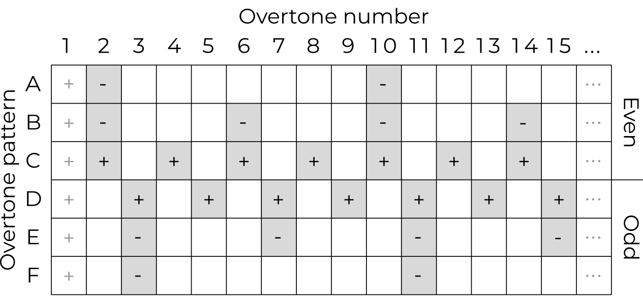
Patterns A–C include even overtones while patterns D–F include odd overtones (note that the 1st overtone, the fundamental, is always implied unless turned off in the Prime Slot tab of the Corner Matrix). Some overtones are present with positive and other with negative amplitudes, making it possible to subtract overtones when blending two patterns together.
Hint
The blend of patterns C and D produces a sawtooth waveform.
The amplitudes of the overtones decrease such that the amplitude of the n-th overtone is either 1/n or -1/n, depending on the sign in the table.
The Noisy overtones pattern (N) generates random noisy content above the fundamental frequency played. It is based on a pink noise (1/f) generator with a resonant high pass filter tuned to the fundamental and can be used on its own or employed as a modulator or carrier in the all blend modes.
Overtone Blend
The Overtone Generators 1 and 2 can be blended together using the Overtone Blend knob. When the knob is in the centre position, the resulting set of overtones equals to Generator 1 (while Generator 2 is ignored).
Outside of the centre position, Blend operates in two different modes: Additive in the left and Modulated in the right half of the range.
Additive mode
When moving the knob to the left from the centre, the two generators are blended additively and the Overtone Blend knob determines the amount of Generator 2 overtones added to or subtracted from the overtones produced by Generator 1 (depending on the +/- signs in the Overtone Generators table), with the leftmost position corresponding to G1+G2.

Modulated mode
When turning the knob to the right from the centre, the two generators are modulated (marked as G1×G2). Five different modulations are available in the Blend Mode tab of the Corner Matrix for each Overtone Blend:
Amplitude modulation (AM),
Phase modulation (PM),
Combination of both (PM+AM),
Phase distortion and amplitude modulation (PD+AM), and
Reversed PD+AM (rPD+AM).
In the Amplitude modulation mode, Generator 1 and Generator 2 are amplitude cross-modulated at the audio rate.

In the Phase modulation mode, Generator 1 is a carrier and Generator 2 is a modulator while the Overtone Blend knob determines the amount of the modulation.

In the Combined PM+AM modulation mode, Generator 2 frequency-modulates Generator 1, and then the result is audio-rate amplitude cross-modulated between the frequency-modulated Generator 1 and the original Generator 2.

Finally, the Phase distortion followed by amplitude modulation mode applies a non-linear phase curve on Generator 2, which results in a time-domain “squeeze” of the waveform. The result is then cross-modulated using audio-rate amplitude modulation.

The PD+AM mode is complemented by a reversed PD+AM (or rPD+AM) mode with a reversed phase curve.

Corner Matrix
The Corner Matrix is accessible on the Orbiter screen
through the Corner Matrix button and allows for
selection of the Corners under editing (with Single or Multi selection possible),
configuration of the Randomizer (Corners, Matrix or Both and Selected or All Four),
versatile configuration of four independent filters (each filter can be placed to any point in the synthesis engine pipeline or bypassed), available in the Filters section,
configuration of the fundamental frequency (prime) slot, available in the Generators section,
selection of the modulation (G1×G2) mode for each Overtone Blend, available in the Generators section, and
individual detuning of all Overtone Generators, also available in the Generators section.
Hint
The behaviour of the Corner Matrix button can be configured in Global settings.
Filters
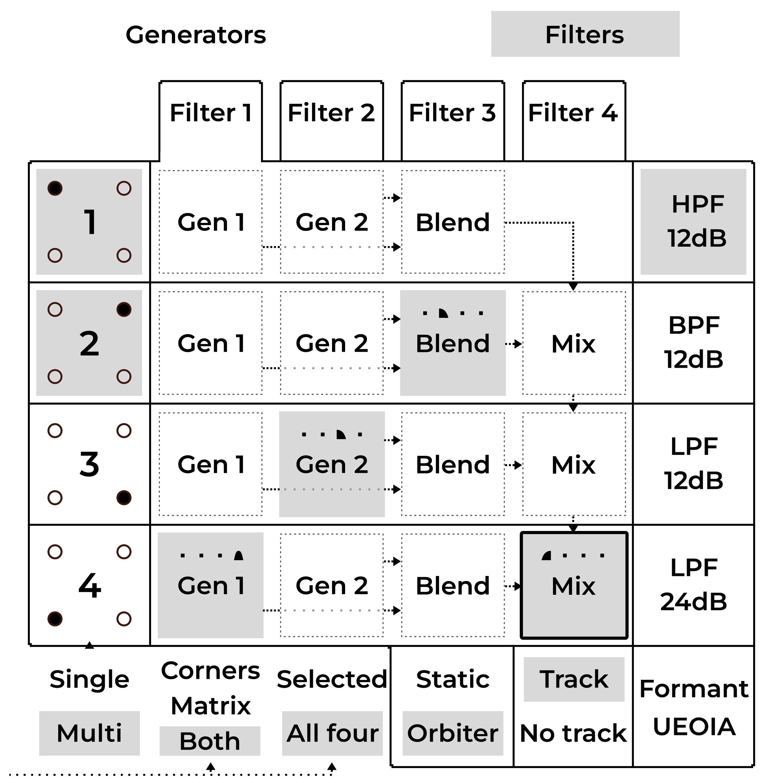
The Filter Matrix allows for configuration of four independent filters. The picture below shows the Corner Matrix interface with four tabs representing each filter and four rows corresponding to each Corner.
Hint
Notice the signal flow of the corners pipeline: the signal is cascading down in such a way, that if a filter is placed on the Mix element, that filter will process the sum of all previous corners’ outputs.
To select Corners for editing, tap one or more of the buttons (labeled 1 to 4) in the first column. The selected Corners can then be controlled by the five Corner parameters knobs just below the display.
To slot a filter, select one of the four filters on the tabs (labeled Filter 1 to Filter 4) and then tap one of the elements in the Corner Matrix. The filter is then placed between the selected element’s output and the next element’s input, as an insert.
In this particular example, Filter 1 is currently under editing and it is configured as a high-pass filter tracking the fundamental frequency of played notes. Filter 2 is placed after Blend of Corner 2, Filter 3 is placed after Generator 2 of Corner 3 and Filter 4 is placed after Generator 1 of Corner 4 – the number of the filter is always indicated by one of the four icons for convenience. Two Corners 1 and 2 are selected, which means their values are changed by the five knobs just below the display.
Hint
It is possible to cycle through the selected Corners/Filters by entering the Focus mode (this temporarily bypasses the Single or Multi selection).
Filter types
Five different filter types are available:
 12dB/oct High-pass filter passes frequencies above Filter Cutoff
(and attenuates frequencies below the cut-off frequency).
12dB/oct High-pass filter passes frequencies above Filter Cutoff
(and attenuates frequencies below the cut-off frequency). 12dB/oct Low-pass and
  24dB/oct Low-pass filters pass
frequencies below Filter Cutoff.
24dB/oct Low-pass filters pass
frequencies below Filter Cutoff. 12dB/oct Band-pass filter passes frequencies inside a band with its
centre frequency defined by Filter Cutoff.
12dB/oct Band-pass filter passes frequencies inside a band with its
centre frequency defined by Filter Cutoff. Formant filter boosts or attenuates frequencies selectively as
to emulate the resonance of different vowels.
The Filter Cutoff parameter aligns the filter with the U-E-O-I-A vowels,
while Filter Resonance controls the filter’s amount.
Formant filter boosts or attenuates frequencies selectively as
to emulate the resonance of different vowels.
The Filter Cutoff parameter aligns the filter with the U-E-O-I-A vowels,
while Filter Resonance controls the filter’s amount.
A filter can be configured to either Track the played notes (so the cut-off frequency is relative to the fundamental frequency of the note) or interpret the cut-off frequency as an absolute value.
If a filter is Static, it is assigned to one specific Corner of the Orbiter (Filter 1 to Corner 1 etc.), which means its properties are always controlled by the specific Corner’s parameter no matter where in the Corner Matrix it is placed. Otherwise the parameters Filter Cutoff and Filter Resonance are modulated by the current Orbiter’s position, as shown by the top-most bar of the Resonance and Cutoff indicators at the bottom of the screen.
Hint
By stacking filters on top of each other, they will be processed serially. Filters of the same type and tuning will effectively increase their total cutoff to up to 48dB/oct, but beware of out of control resonances in such scenarios.
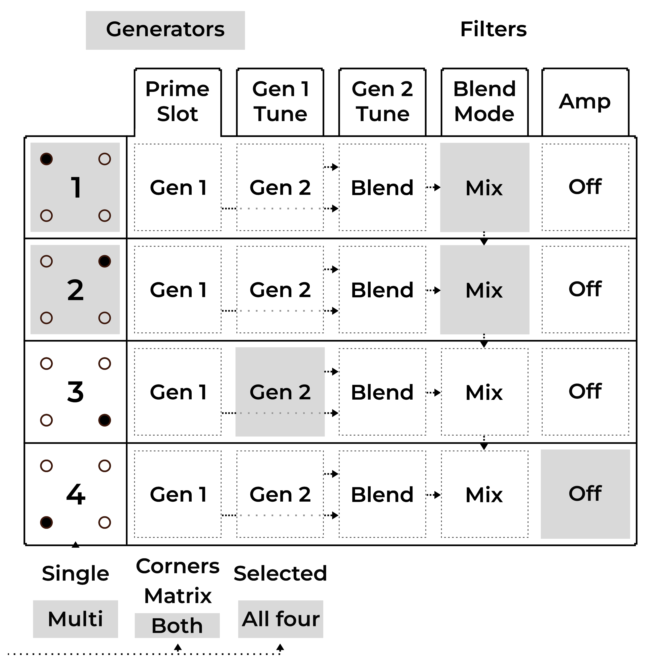
Generators
The Generators section of the Corner Matrix allows of the individual Overtone Generators (two per each corner).
Prime Slot
The Prime Slot tab determines where in the signal chain the fundamental frequency is added.
In this particular example, the fundamental of Corners 1 and 2 is added to the final mix of the corners, the fundamental of Corner 3 is added to the output of its Generator 2 and the fundamental of Corner 4 is not utilised (Off):
Gen Tune
The Gen 1 Tune and Gen 2 Tune tabs allow for individual detuning of all Overtone Generators by a fixed ratio (before the Blend modulation). However, the fundamental frequency remains unchanged.
The fixed ratios 1/2, 1/3, 1/4, and 1/5 correspond to one octave down, one octave and a fifth down, two octaves down, and two octaves and a major third down, respectively.
In this particular example, Generator 1 of Corner 2 is detuned to one third of the fundamental frequency while others are unchanged (1×):

Blend Mode
The Blend Mode tab allows for selection of one of the five modulation (G1×G2) modes modes for each corner. The individual modes are described in the Overtone Blend section.
In this particular example, all corners are using the combined PM+AM mode:

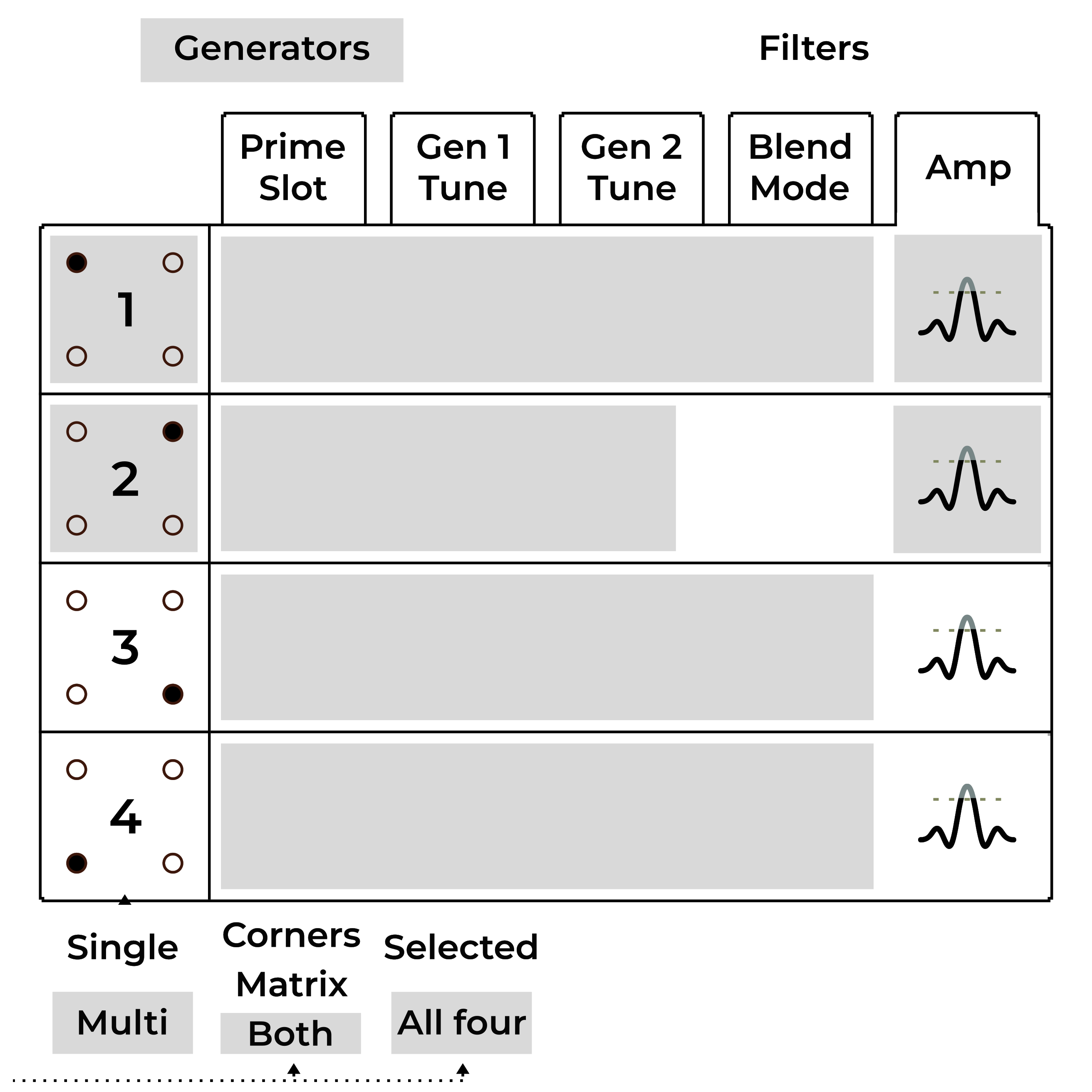
Amp
Finally, the Amp tab allows for individual volume configuration of each corner with an optional per-corner limiter.
In this particular example, corners 1, 3 and 4 are set to the maximum volume, while the volume of corner 2 is lower. Corners 1 and 2 have the limiter enabled.
Randomizer
The Randomizer is available on the Orbiter screen and
allows for randomization of the Corner’s parameters and Corner Matrix.
The Randomize  button generates a new set of parameters for
all selected Corners (and the Corner Matrix) while the Undo
button generates a new set of parameters for
all selected Corners (and the Corner Matrix) while the Undo  button reverts back to the previous state.
The scope of randomization can be either four Corners’ parameters, the Corner Matrix configuration or Both. Moreover, it is possible to restrict the randomization to only the Selected corners as opposed to All Four of them.
Hint
The scope of the Randomizer can be configured in the Corner Matrix.
Polyphony
Vector supports three distinct polyphony modes with different sets of parameters.
|
Mono |
Dual |
Poly |
|---|---|---|---|
Detune |
Stack |
Follower |
Drift |
Glide/Stereo |
Glide |
Stereo Bias |
Stereo Scatter |
Volume |
Stack |
Follower |
– |
Suborbit Offset |
– |
Follower |
– |
Voices |
1 to 16 |
8 |
16 |
Poly Mode
In the Poly Mode, each new note is played by a separate voice, resulting in a 16-voice polyphony. New individual voices can be randomly scattered (panned) across the stereo space using the Glide/Stereo knob and periodically randomly detuned by an amount controlled by the Detune Drift knob.
Dual Mode
In the Dual Mode, each note is played by a separate voice which is complemented by a second follower voice with an altered pitch and amplitude. This mode thus effectively reduces the maximum number of concurrently playing voices to eight.
The pitch of the follower voice can be adjusted by the Detune Follower
knob while the amplitude is controlled by the Follower Volume slider on the
Effects screen  .
.
The Suborbit Offset slider controls the suborbit phase offset between the main and the follower voice while the Glide/Stereo knob controls the stereo bias of the main voice (with the 50% value representing no bias). When the main voice is biased to the left, the follower voice is panned to the right and vice versa.
Mono Mode
In the Mono Mode, all voices form a voice stack dedicated to playing one note, with each of the voices being slightly detuned by an amount derived from the Detune Stack knob and panned (evenly spread across the stereo space).
The number of available voices can be reduced using the Voices slider on the
Effects screen , which when reduced to a single voice makes
Vector act as a monophonic synthesizer. The Stack Volume controls the
relative amplitudes of the voices in the stack except for the first voice.
The Glide knob controls the portamento time (i.e. the amount of time it
takes to change the oscillator pitch between two overlapping notes).
Glide can thus be used to play a legato effect by pressing a note followed by
another note without releasing the first one.
Legato can be also played by the Arpeggiator if two adjacent steps are
chained  together.
Arpeggiator
The Arpeggiator records notes from its input and plays them out sequentially in eight steps, with multi-octave transpositions.
The Active switch enables or disables the arpeggiator while the Note Length knob adjusts the length of notes played in each step relatively to the arpeggiator tempo (which is derived from the main Tempo and can be set to different time signatures).
Step Grid
The Effects screen allows for more detailed control over
the arpeggiator. The Step Grid (2) represents the arpeggiator sequence with
octaves spread vertically. It is possible to select octave transposition for
each step or to disable it completely. The velocity of each step in the sequence
can be adjusted using the sliders below (3). The adjacent notes can be chained
together (1) into one.

The chaining either generates legato in the Mono polyphony mode or joins two steps with equal octaves in the Dual and Poly modes.
The arpeggiator note memory can be temporary (with arpeggiator playing only the
currently pressed notes), Latched  (notes stay in memory even
after they are released), or Step-recorded
(notes stay in memory even
after they are released), or Step-recorded  .
The order in which the notes are played out can be sorted Up
.
The order in which the notes are played out can be sorted Up  ,
Down
,
Down  or Shuffled
  .
.
Randomization
To make the pattern produced by the arpeggiator vary over time, some of the parameters can be set to be automatically randomized while the arpeggiator is playing:
Octave Walk
 periodically alters octave transpositions of
the individual steps.
periodically alters octave transpositions of
the individual steps.Chain Walk
 alters the steps’ chaining.
Humanize alters note lengths.
Hints
To feed notes into the arpeggiator, the Feed Direction switch must be set to Arp or Both and the Feed button has to be active (indicated by flashing LED), as described in section Feed.
Depending on the Feed configuration, the arpeggiator can play in the background.
To release notes from the arpeggiator, press the Latch
button twice.At least some octaves in the grid have to be enabled in order to make the arpeggiator output notes.
The arpeggiator can be fed from a separate MIDI channel as described in MIDI configuration. It can be also configured to output notes to a selected MIDI channel.
Effects
Vector has multiple effects connected to the output stage of the main mix of all Corners. Unlike Corners, the effects are independent of the Orbiter position.
The Effects’ parameters are accessible on the two bottom-most rows of encoders
(depending on the Control switch configuration for some of
them) with additional options available on the Effects screen
.
Hint
To hear the output of Reverb, Chorus or Delay, the respective knob in the Mixer section has to be turned up.
Vibrato and Tremolo
Vibrato and tremolo are effects which periodically modulate the pitch and amplitude of the played notes. They are characterized by two parameters, depth and speed.
Vibrato Depth controls the amount of the pitch variation and Tremolo Depth controls the amplitude variation, while Vibrato Speed and Tremolo Speed control the frequency of each variation.
The speed can be synchronized with the main Tempo using one of the switches in the Sync section.
Hint
To disable Vibrato or Tremolo, turn the respective Depth knob to zero.
Drive
Drive is derived from an overdrive effect known from guitar amplifiers where the input signal is saturated so that clipping occurs, adding a number of new harmonics to the signal.
The effect consists of a band-pass filter followed by a saturator, wired in parallel. The filter’s cut-off frequency is controlled by the Drive Colour knob, while Drive Amount controls both the input gain of the saturator and the contribution of the Drive effect to the final mix.
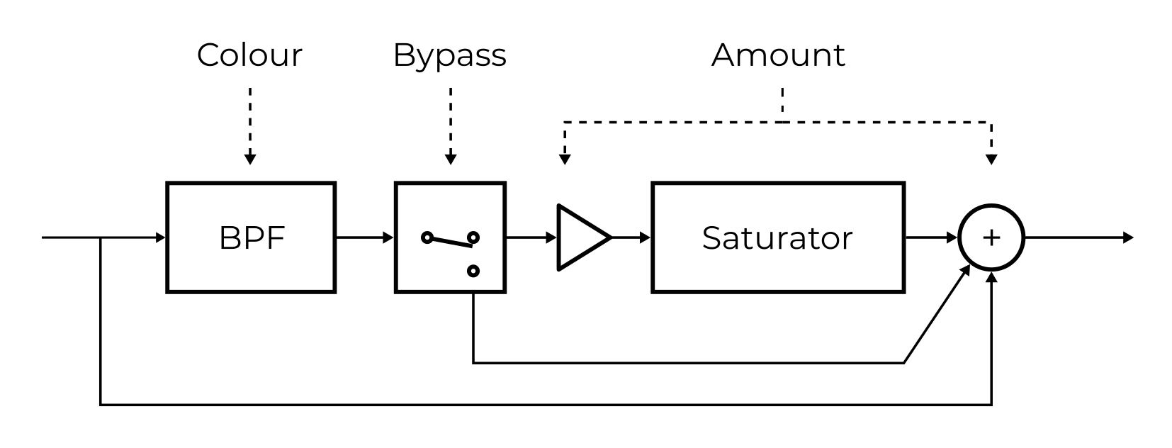
The Bypass  button on the Effects screen
disables the saturator. In this case, the Drive Amout only sets the mix
level of the effect’s band-pass filter.
button on the Effects screen
disables the saturator. In this case, the Drive Amout only sets the mix
level of the effect’s band-pass filter.
Chorus
Chorus mixes together sounds played back at different pitches, resembling the effect of a choir or an orchestra section. It consists of several variable delay lines and an optional band-pass filter which are characterized by three parameters:
Chorus Depth controls the amount of detuning.
Chorus Speed determines the speeds of the variable delay lines (this can be synchronized with the main Tempo using one of the switches in the Sync section and additionally slowed down
 by a factor of two).
Chorus Colour controls the band-pass filter’s cutoff frequency if the filter is enabled
 .
.
The effect can operate in mono or stereo. If the Stereo Mode  is
enabled, the effect’s output is different for the left and right channels.
is
enabled, the effect’s output is different for the left and right channels.
Delay
The Delay effect adds a delayed version of the audio signal to the final mix.
Delay Time controls how much is the signal delayed and Delay Feedback
controls the amount of output signal being fed back into the delay.
Furthermore, Delay can be set to a dotted time  and the feedback
signal can be routed through an optional Band-pass Filter .
and the feedback
signal can be routed through an optional Band-pass Filter .
If the Delay Feedback is set to a maximum (and the band-pass filter is
disabled), the Delay effect behaves as a looper. If the feedback
is set to zero, the internal audio buffer is fully cleared after one
Delay Time period. If needed, the buffer can be cleared manually
 .
.
Delay can operate in mono or stereo. In the Stereo Mode , the
effect’s output is different for the left and right channels (“ping-pong”).
Hints
To feed notes into the delay, the Feed Direction switch must be set to Delay or Both and the Feed button has to be active (indicated by flashing LED), as described in Feed.
Try recording a sample played by the Arpeggiator and then play it over a different sequence.
Reverb
Reverb simulates the reverberation of sound in a physical environment caused by reflections from the boundaries (walls of a concert hall for example).
Reverb Size increases the persistence of the processed sound (in the same way as larger rooms produce longer reverberation), while Reverb Colour controls the cutoff frequency of a band-pass filter at the effect’s output.
The effect operates in stereo mode so its output is different for the left and right channels.